Top 10 Common Signs of Hydraulic Pump Failure, Field Checklist for Fast Diagnosis
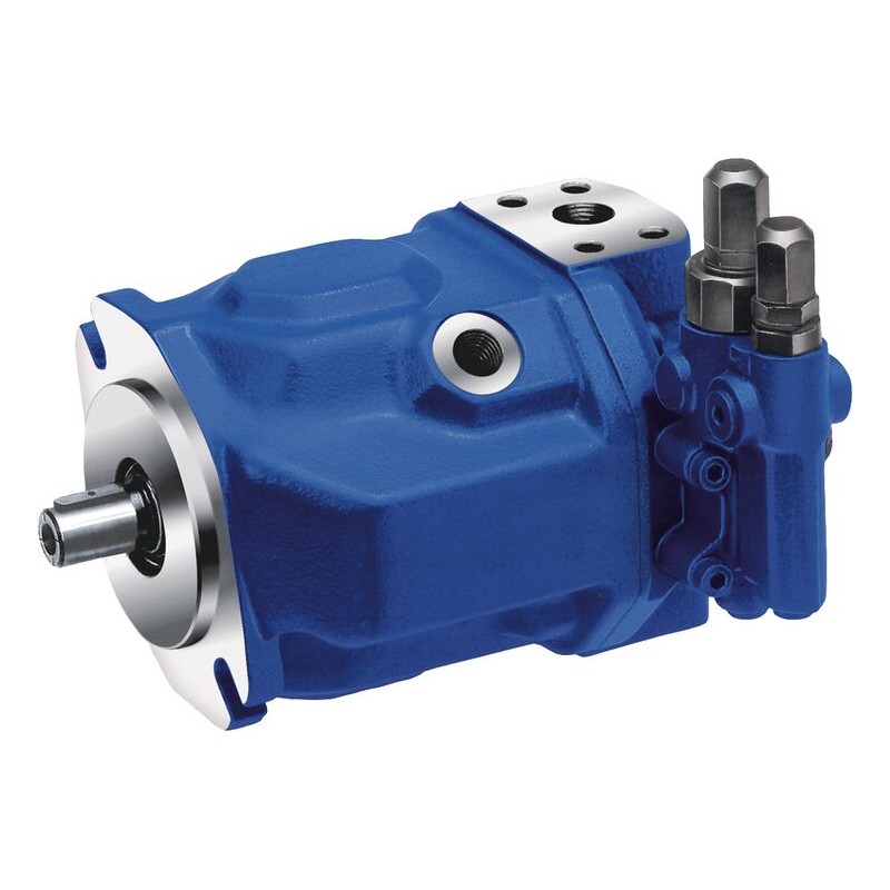
Hydraulic pumps are the heartbeat of heavy equipment used in construction, metro works, bridges, piling, mining, onshore and offshore oil and gas, and marine support operations. When the pump starts to fail, the symptoms usually show up first in the field as heat, noise, slow cycles, unstable pressure, or contamination. Catching those early signs can prevent downtime, secondary damage to valves and motors, and costly cleanup.
This guide is written as a practical, on site, Top 10 list for technicians and supervisors. It includes what you see, what it often means, and a fast checklist you can run with basic instruments like a pressure gauge, flow meter, IR thermometer, and a clean sampling bottle. It is especially relevant for piling rigs, industrial hydraulic power packs, marine deck machinery, cranes, and auxiliary systems where precision and uptime matter.
Before you start, safety and setup
- Lock out and tag out whenever possible. Depressurize circuits before cracking any lines.
- Verify the correct hydraulic oil grade and that the tank level is within the operating range.
- Work clean. A small amount of introduced dirt can mask the real failure and create a new one.
- Record ambient temperature, oil temperature, and machine hours. This helps separate normal cold start behavior from real faults.
Top 10 common signs of hydraulic pump failure, and what to check
1) Abnormal noise, whining, growling, or rattling
Unusual pump noise is one of the earliest warnings. A high pitched whine often points to aeration or cavitation, while a deeper grinding noise can indicate bearing damage or internal scoring.
- Likely causes: Cavitation from restricted inlet, clogged suction strainer, collapsed suction hose, low oil level, wrong viscosity, air leaks at fittings, worn bearings, misalignment with the drive.
- Fast checks: Inspect suction line for kinks and soft spots, check inlet vacuum if you have a gauge, verify tank level, listen for changes when you crack the filler cap slightly, check coupling condition and alignment.
- What to record: When noise appears, cold start only or always, any recent filter changes, any hose replacement, and whether noise changes with load.
2) Slow actuators and reduced cycle speed
When cylinders, winches, or motors slow down, many teams blame the pump immediately. In reality, the pump could be fine and flow may be bypassing through relief valves, worn directional valves, or internal leakage in actuators. Still, a worn pump is a common root cause in high hour systems.
- Likely causes: Pump wear causing low volumetric efficiency, relief valve stuck partially open, incorrect pump control settings, clogged filters, suction restriction, oil too hot and thin, or air in oil.
- Fast checks: Compare commanded RPM to actual engine or motor speed, check filter restriction indicator, measure system pressure under load, measure case drain flow on piston pumps if applicable.
- Rule of thumb: If pressure reaches spec but speed is low, suspect low flow. If speed is ok but force is low, suspect low pressure or a relief path.
3) Pressure fluctuations, hunting, or unstable gauge readings
Pressure that oscillates can cause jerky motion and poor control, which is dangerous during lifting, pile driving alignment, and marine deck operations. A healthy system usually shows stable pressure for a stable load.
- Likely causes: Air entrainment, cavitation, compensator instability, worn swash plate components, sticking control piston, contaminated pilot circuit, relief valve chatter, suction leaks.
- Fast checks: Bleed air where the OEM allows, inspect return flow for foam, sample oil for bubbles, verify pilot pressure and cleanliness, check that the correct orifice and damping settings are installed.
- What to watch: Fluctuations that increase as oil warms often point to internal leakage or control issues rather than cold oil viscosity.
4) Excessive heat, hot reservoir, hot pump case, or burnt odor
Heat is wasted energy. Overheating accelerates oil oxidation, destroys seals, and increases internal leakage, creating a cycle of worsening performance. In offshore and marine environments, cooling water flow and heat exchanger fouling add additional risk.
- Likely causes: High internal leakage in pump, relief valve continuously bypassing, incorrect oil viscosity, cooler performance issues, blocked airflow, fouled seawater side heat exchanger, slipping drive coupling.
- Fast checks: Use an IR thermometer to compare pump case temperature, tank temperature, and cooler inlet and outlet temperatures. Verify relief valve is not dumping at neutral. Check fan direction and cooler cleanliness.
- Interpretation: A pump case that is much hotter than the tank can indicate pump internal leakage or bearing friction.
5) Foamy oil, milky oil, or visible air bubbles
Foam reduces lubrication and causes compressibility, which makes controls spongy and increases noise. Milky oil usually indicates water contamination, which can cause corrosion, poor lubrication, and rapid wear.
- Likely causes: Low oil level allowing vortexing at return, suction leaks, incorrect return line routing, damaged baffles, water ingress from cooler leaks, humidity condensation, open hatches in marine environments.
- Fast checks: Check tank level at rest, inspect return line below oil level, tighten suction clamps and fittings, perform a simple crackle test for water if you are trained, and schedule lab analysis.
- Immediate action: If water contamination is confirmed, stop and correct the ingress source, then dehydrate or replace oil before continuing heavy duty operation.
6) Frequent relief valve opening or inability to reach rated pressure
A pump that cannot build pressure under load may have worn internals or could be starved. However, a faulty relief valve or a major internal leak in an actuator can look similar.
- Likely causes: Pump wear, cracked valve plate, damaged pistons, sheared shaft, relief valve set too low, relief valve stuck open, load holding valve leakage, major cylinder bypass.
- Fast checks: Verify relief setting with a calibrated gauge, isolate circuits if possible, test pressure rise rate, check for excessive case drain flow in piston pumps, and inspect for bypass heating at the relief manifold.
- Decision point: If relief setting is correct and pressure still cannot be achieved, move toward flow testing and internal leakage checks.
7) Metal particles in filters, strainers, or magnetic plugs
Shiny debris is one of the most serious signs. Bronze, steel, and aluminum particles can indicate different wear locations. Early detection can prevent a total system contamination event, especially in complex offshore power units and piling power packs.
- Likely causes: Bearing failure, gear pump scoring, piston shoe wear, swash plate damage, cavitation erosion, contamination induced abrasion.
- Fast checks: Cut open the return filter if permitted, check the suction strainer carefully, inspect magnetic plugs, and document the particle type and amount. Send a sample for lab analysis.
- Field rule: If you see heavy metal, assume downstream valves and actuators are at risk. Plan containment, flushing, and component isolation.
8) Increased case drain flow, or case drain line overheating
For many axial piston pumps, case drain flow is an excellent health indicator. As internal clearances open up from wear, leakage increases, and the case drain becomes warmer and higher in flow.
- Likely causes: Worn rotating group, damaged valve plate, seal damage, overpressure events, prolonged operation at high temperature.
- Fast checks: Measure case drain flow at a specified operating condition and compare to OEM limits. Feel and measure case drain line temperature relative to tank return.
- Important: Do not cap a case drain line. Backpressure can destroy the pump quickly.
9) Jerky motion, vibration, or loss of fine control
Operators often report that the machine feels rough, the boom shakes, or the winch surges. While valve issues and air can cause this, a failing pump that cannot provide smooth flow, or a control that is sticking, is a frequent contributor.
- Likely causes: Air in oil, pump control instability, cavitation, poor inlet conditions, contaminated proportional control circuit, worn pump leading to flow ripple.
- Fast checks: Observe motion at different RPM and loads, watch the pressure gauge during the jerk event, check oil for foam, verify pilot pressure stability and filter condition.
- Operational risk: Jerky hydraulics increase shock loads on structures, pins, and ropes, and can become a safety issue during lifting and positioning.
10) Repeated seal leaks, shaft seal blowout, or oil weeping at the pump
Leaks are sometimes treated as a minor nuisance. For pumps, leaking seals can indicate misalignment, excessive case pressure, worn bearings, or pressure spikes. In marine environments, salt and corrosion can also damage sealing surfaces.
- Likely causes: High case drain backpressure due to restricted return, blocked case drain line, worn bearings causing shaft wobble, misaligned coupling, pressure spikes, incorrect seal material for oil type and temperature.
- Fast checks: Confirm case drain routing and backpressure, inspect coupling and mounting bolts, check for shaft play, inspect for corrosion or pitting, verify breathers are working and tank is not pressurizing.
- Do not ignore: A seal leak that suddenly worsens can be the last warning before a bearing failure.
Field checklist for fast diagnosis, step by step
Use this checklist to move from symptoms to evidence. The goal is to identify whether the pump is failing, whether the pump is being damaged by poor inlet conditions, or whether the fault lies elsewhere in the circuit.
- A. Operator interview and quick symptom map
- What changed first, noise, speed, heat, or pressure?
- Did the issue start after maintenance, hose replacement, filter change, or oil top up?
- Is the problem only at cold start, only when hot, or constant?
- Is one function affected or all functions?
- B. Visual inspection, 5 minute walkdown
- Tank level, oil color, foam, and smell.
- Loose suction clamps, cracked hoses, flattened suction hose, and missing O rings.
- Return line discharge position, baffles, and breather condition.
- Evidence of relief valve bypass heating, hot spots on manifolds, and scorched paint.
- Leaks at pump shaft seal and case drain fittings.
- C. Temperature survey
- Measure tank, pump case, suction line near pump, pressure line near pump, and cooler in and out temperatures.
- If the pump case is significantly hotter than the tank early in operation, suspect internal leakage or mechanical friction.
- If the cooler delta is low, suspect cooler fouling, fan issues, or low cooling water flow.
- D. Pressure checks
- Verify main relief setting with a calibrated gauge at a safe test point.
- Check standby pressure and loaded pressure, note fluctuations.
- If available, check inlet vacuum against OEM limits to detect suction restriction.
- E. Flow and leakage checks
- If you have a flow meter, measure pump output flow at a defined RPM and pressure, then compare to spec.
- For piston pumps, measure case drain flow at operating temperature and pressure, compare to OEM limits.
- If flow is low and case drain is high, the pump is likely worn internally.
- If flow is low and inlet vacuum is high, the pump may be starved, fix inlet conditions first.
- F. Oil cleanliness and contamination checks
- Check filter restriction indicators and service history.
- Take an oil sample from a live zone, not the bottom sludge, and send for ISO cleanliness, water content, and wear metals.
- Inspect magnetic plugs and strainers for metal, document findings with photos.
- G. Decision and next action
- If evidence points to inlet starvation, correct suction restrictions, air leaks, oil level, and viscosity, then retest.
- If evidence points to pump wear, plan a controlled shutdown, avoid contaminating the entire system, and schedule pump overhaul or replacement.
- If evidence points away from the pump, isolate suspect valves or actuators with targeted tests rather than swapping the pump unnecessarily.
Common field mistakes that delay diagnosis
- Changing the relief valve setting to mask low flow. This can cause heat, damage, and safety risks.
- Replacing the pump without fixing suction leaks or clogged strainers. The new pump can fail quickly.
- Skipping oil analysis after a metal finding. Without contamination control, valves and motors can fail later.
- Testing pressure only. Pressure alone does not confirm pump health, you need flow and leakage information.
When to stop operation immediately
- Sudden loud mechanical noise or grinding from the pump.
- Rapid temperature rise, burnt smell, or smoking oil.
- Heavy metal particles found in filters or strainers.
- Loss of critical function that affects lifting, braking, steering, or marine safety systems.
How SunTech Technical Services Co. can support
In high consequence environments like piling works, industrial hydraulics, and marine project support, the fastest solution is often a structured diagnosis followed by the right repair plan. SunTech Technical Services Co. supports PPU troubleshooting, industrial hydraulics, parts supply, and engine related services for heavy equipment. If you provide your pump model, system pressure, oil type, temperatures, and the checklist readings above, a technician can quickly narrow the fault, recommend corrective action, and help you restore precision, power, and performance.
Quick summary
- Noise, heat, foam, unstable pressure, low speed, and metal debris are the most common early warnings.
- Always verify inlet conditions and oil cleanliness before condemning a pump.
- Use measured data, pressure, temperature, flow, and case drain, to confirm pump condition.
